
Building a hobby robot without model airplane servos.
Single degree of freedom: A.k.a. "Axis of motion." This refers to how many different directions a robotic joint can move in. Because it moves in a single plane, the human elbow has only a single degree of freedom. The human body equivalent of a multiple degree of freedom would be a neck. A person can usually look up and sideways at the same time.The arrows there show how the elbow joint can move back and forth, and are also handy to express the ~120 degree workspace. (a.k.a. the range of motion.) A workspace is defined as the area a robot can reach and thus do work in. In this case, the elbow can move a maximum 120 degrees (which is actually pretty good.).
A drive train is a system used to convey force from one place to another, in this case the motor to the joint. A worm gear assembly is hard to explain, but it is basically a screw which meshes with the teeth of a gear. In this way it translates force across a perpendicular, and is also good because it turns a fast, low torque rotation into a slow, higher torque movement. The thing ended up powerful enough to do little robot pull-ups!
Worm gear trains are also whatcha call "self locking." In this case the motor can move the elbow, but the elbow can't move the motor, which is handy: When the motor stops, so does the elbow, otherwise it would sag when the motor was disengaged.

That micro piezo speaker there is so the robot can tell you what's up by beeping at you (YES - like R2D2.) More on that subject in the "brains!" page.
A closed loop system is any system which has some feedback information about where it is at, how far it's gone, and/or how fast it's going. For example, the speedometer and odometer on a car make for a closed loop system.
Conversely, an open loop system just zips around willy nilly without any idea where it's at. Most of the cheaper robot kits available are open loop. Some of them even advertise the fact like it's some really cool feature you've never heard of. "Operates open loop! Only $50.00!" Yeah, like "Completely empty can of soda!"
A shaft encoder is something you use to close that loop we're talking about. Shaft encoders are devices which sense by some means where the joint is at, how fast it's going, and/or how far it's gone. They come in a few different flavors, the two most common being "incremental" and "absolute." An incremental encoder, as it's name would suggest, simply counts the number of revolutions, or fractions of revolutions a joint has gone, ("we've gone five blips so far.") like your odometer on a car.
An absolute encoder is a sensor which can tell exactly what degree of rotation a joint is at. I built this feature into both the joints of my robot so that I could tell it something like "turn left to 90 degrees and look up 45 degrees." The encoder information is also used to prevent the elbow from trying to turn too far and bashing itself into pieces. Lastly, I wanted this feature because it's cool.
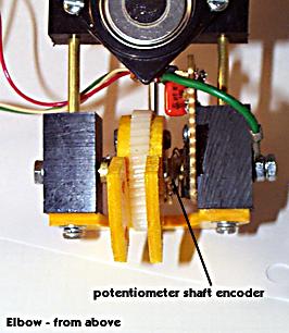
In the elbow, I worked it out with the pieces of a dissasembled potentiometer (pot.) The potentiometer body sits around the shaft, and a spring/wire is dragged over the surface of it.
The main brain of the robot, the Basic Stamp 2, can measure the resistance across it. I won't bore you further with a lecture on this process, but I will complain to you a bit about this setup:
It turns out that figuring a variable resistance created by dragging a wire over a semiconductor isn't exactly as accurate as it could be. It's maybe like trying to measure the wingspan of a dragonfly with a c-clamp. You'll get an answer, eventually. This is without even mentioning the fact that analog electronics components change states due to temperature and/or how they happen to be feeling at the time.
What I had to do to solve this little quandary was create a feature in the software which I like to call "oversampling" because it sounds cool. It samples the circuit a bunch of times and compares the answers before it makes a decision. Drop me a line if you're curious about the code.
Voila!