The Parallax Basic Stamp Microcontroller
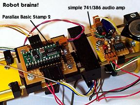
Here you can see the Parallax BS2 on a carrier board I built for it & also the audio amp. The BS2 is a microcrontroller with16 in/out (I/O) pins, which, for my robot, was not enough (see below.)The BS2 is programmable in a version of the Basic language, which is rather simple and easy to learn, but offers some pretty powerful features. In particular (for you technophiles,) it has some rather sexy bit and byte-specific variable-aliasing & handling features.
Like I said on the concept page, robotics is all about communication, and the BS2 is the hub of this activity. It can communicate digitally to transistors & all flavors of integrated circuits (a.k.a. "ICs" a.k.a. "chips")
It can also communicate somewhat in analog: it can output a PWM (pulse width modulation) signal which will (among other things) amount to an analog voltage output, and with the help of a capacitor and a resistor, can take analog measurements of resistance (good for sensors.)
I decided to have EL BO communicate to the outside world via beeps instead of trying to mount a huge & expensive visual display to it. Here's how:
PWM also amounts to a nice range of frequencies, which can be made audible. These frequencies are sent to an audio amp which outputs it through a speaker.
The amplifier I built is from the Forrest Mims Scrapbook, with some modifications (the robot has no negative power supply) and with a filter circuit straight out of the BS2 manual.
Click here for the Parallax home page to find more info on the BS2.

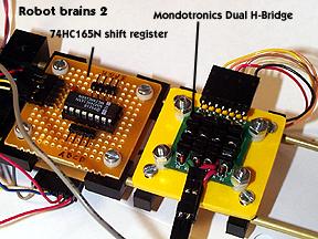
In the section above I mentioned that I maxed out my I/O pins on the BS2. The "shift register" in the picture is a very simple circuit I built to add some more. At the cost of 3 I/O pins on the BS2 you can get eight digital inputs. More flexible, sexy, and bigger solutions exist, but after some consideration I chose the shift register because it offered easy interface, a rock bottom part count (you don't need any external resistors, capacitors, oscillators, etc.,) and cost a friendly 50 cents!
This particular shift register is officially known as a "8 bit parallel to serial shift register." This refers mostly to the communication method it uses. It turns parallel information into serial.
Serial is a communication method where seperate signals are sent sequentially one after the other across one wire. There are a gazillion serial communication protocols, which use timing, error correction math, clocking, signal frequencies, "hand shaking," etc. The serial communication device you are probably most familiar with is your mouth. You say a series of words one word at a time, and meaning is somewhat dependent on sequence.
For you technophiles, the serial protocol used by this chip is synchronous "MSBPRE" (which stands for "most significant bit first pre-clock pulse mode."
So, in the end, this chip takes information from 8 wires and uses 3 wires to hand that info to the BS2.
An H-Bridge is a circuit designed to take a small signal (go forward, go reverse) from a microconroller and turn it into something which can power a motor in the desired direction. I ended up buying a packaged H-Bridge after trying & frying three or four home built ones.
Click here to visit the Mondotronics robot store.

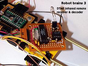
The DTMF infrared remote control receiver & decoder.
So are you tired of reading about communication yet? Well, buckle in because here is more more more. Since the robot was going to be moving around all the time, it would be a pretty sticky proposition to have to hit keys any time you wanted it to do something else (like turn off.) Thus I figured it would be a good idea to build a remote control system for it. What looked like the most hearty, simple, and cheap method at the time was a DTMF based infrared remote.
I built a seperate transmitter which generates the tones and transmits them via IR light emitting diodes (LEDs.) The board in the picture has a sensor which picks up that light, turns it into an electrical signal, which is then amplified and finally, decoded by a chip specially designed to do so.
The chip will then tell your microprocessor what number corresponds to the tone it just heard. Just for the record the chip communicates this information in parallel.