Building a hobby robot without model airplane servos.
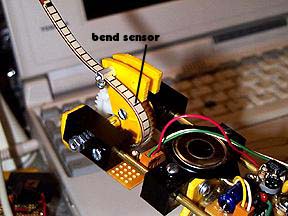
Here is a picture of the elbow with the new bend sensor absolute shaft encoder.Those of you who read all the way through my probably over-technical description of the elbow and elbow shaft encoder will doubtlessly remember that I was pretty dissatisfied with the performance of my home-brew potentiometer based shaft encoder.
There were too many moving parts: the thing got progressively worse from testing, general fiddling, and mounting heavier objects on the forearm.

So I bought a bend sensor. They are
4.5 inches long by a quarter inch wide, and start at about 10K ohms. The
resistance increases as the sensor bends.
Somebody on the web (lost the link, sorry!) who has played with them a bit added the info
that the change in resistance compared to change in bend is non-linear up to a bend of about 15 degrees and suggested pre-loading to solve this problem.

There were other problems involved as well, like how am I going to fit a 4.5 inch long object into an elbow which is only about 2" x 2" x 1" and packed with other stuff? And how am I going to utilize something which doesn't stretch, needs to be secured at both ends, but also needs to be used without bisecting the drive shaft? And how do I install this thing so it doesn't break or get pulled out the millionth time it is flexed by the joint?
The solution, arrived at three days later, was to install it like a watch spring, all coiled up.

A picture I drew of the plan, which should give you the general idea.
This design basically solved all the above problems and even better, has supplied me with a cheap absolute shaft encoder which is linear enough for my needs and is repeatable. In fact, I was able to take the oversampling routines out of my driver software without decreasing the accuracy of this solution.
By the way, I finally did find a commercially made optical absolute shaft encoder which is for sale to the public in small quantities. For $250 bucks! Dang! Of course, that's for 32 bits of encoder info, but even still... Dang!

The shoulder joint also needed some improving. Here is a photo of the newest solution. I ended up creating a disk on a tripod with the shaft going through the middle. It is much less wobbly now.
The other huge engineering problem I was faced with was how to get power from the base, through a joint with 360 degrees of freedom, and up into the body of the robot.
Running wires straight to the body would mean that the wires would be dragged around under the robot every time it rotated. Running wires straight through the joint would get them twisted back & forth until they snapped.

Having had so much success with the bend sensor imitating a spring gave me the idea of having the wiring in the joint behave like a spring as well. After all. a spring is a device which spreads stress over its entire body instead of in one tiny place.
Here you can see the result built into the belly of the base. The power wires go from the body of the robot, down through the center of the shoulder joint shaft and are then coiled into a spring before proceeding to the power jack. A certain pal o' mine, who recently gave me a book on building robots, also donated the wire used in this joint, which is especially rigid twisted pair wiring. Thanks man!
While I'm at it, thanks also go to another friend who was also kind enough to give me a cool book on robots.
Here are two cool sites about robots. One about the Mint Cleaner
by Evolution Robotics and another about Robotic Toys.
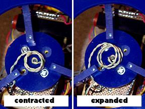
Here you can see it in action (there is a plate which encloses this area.) As the robot rotates in one direction, the wire spring contracts. As the robot rotates the other direction, it expands. Voila! The stress of the rotation is spread out over about three inches of wire.
Obviously, this spring system will max out at about 2 full rotations, but that's a problem I can deal with in the software.

Eventually, I will probably be posting some MPEGs and/or Quicktime movies of Project Elma Beaucoups, but until then this will be about as good as it gets. This is a four second exposure (shot in the dark) of EL BO swivelling from its "home" position (0,0) to around 90 degrees elbow, 120 degrees shoulder.
'Til next time.